Fabricating wide pegs for XT600
October 28, 2024
Preparing for a light enduro/off road event I wanted to have wider pegs for my 1987 Yamaha XT600. This makes it less straining to stand up for extended periods of time.
It is of course possible to buy wider foot pegs, but as I wanted them to be steel, for the added strength they also became more expensive than I wanted. This gave me the idea to just make them myself.
I already had the original steel ones that I could fabricate an “outer ring” for.
So this was the plan. Fabricate an “outer ring” for the original ones and weld them.
My approach would be to cut a flat piece of 2,5 mm steel plate to the length required to reach all the way around the original ones. It would be “double” width as I would then drill holes along the middle of it and finally cut it into the two corresponding parts, one for each side. This hopefully would make them more uniform than doing them one by one.
First the rough sketch having traced the original foot peg as the inner half-circle I drew the “outer ring” somewhat free hand, which gave me a measure of a little under 18 cm for the full length.
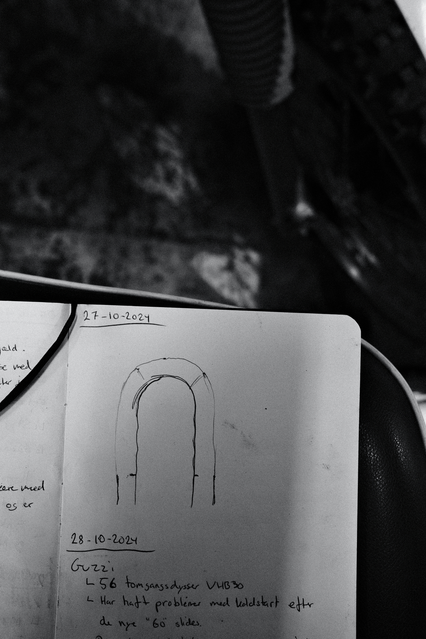
I then cut out a matching piece of 2,5mm steel plate in 3 cm width as each individual ring should have a height of just under 1,5 cm (as some height would be lost by the cut itself).
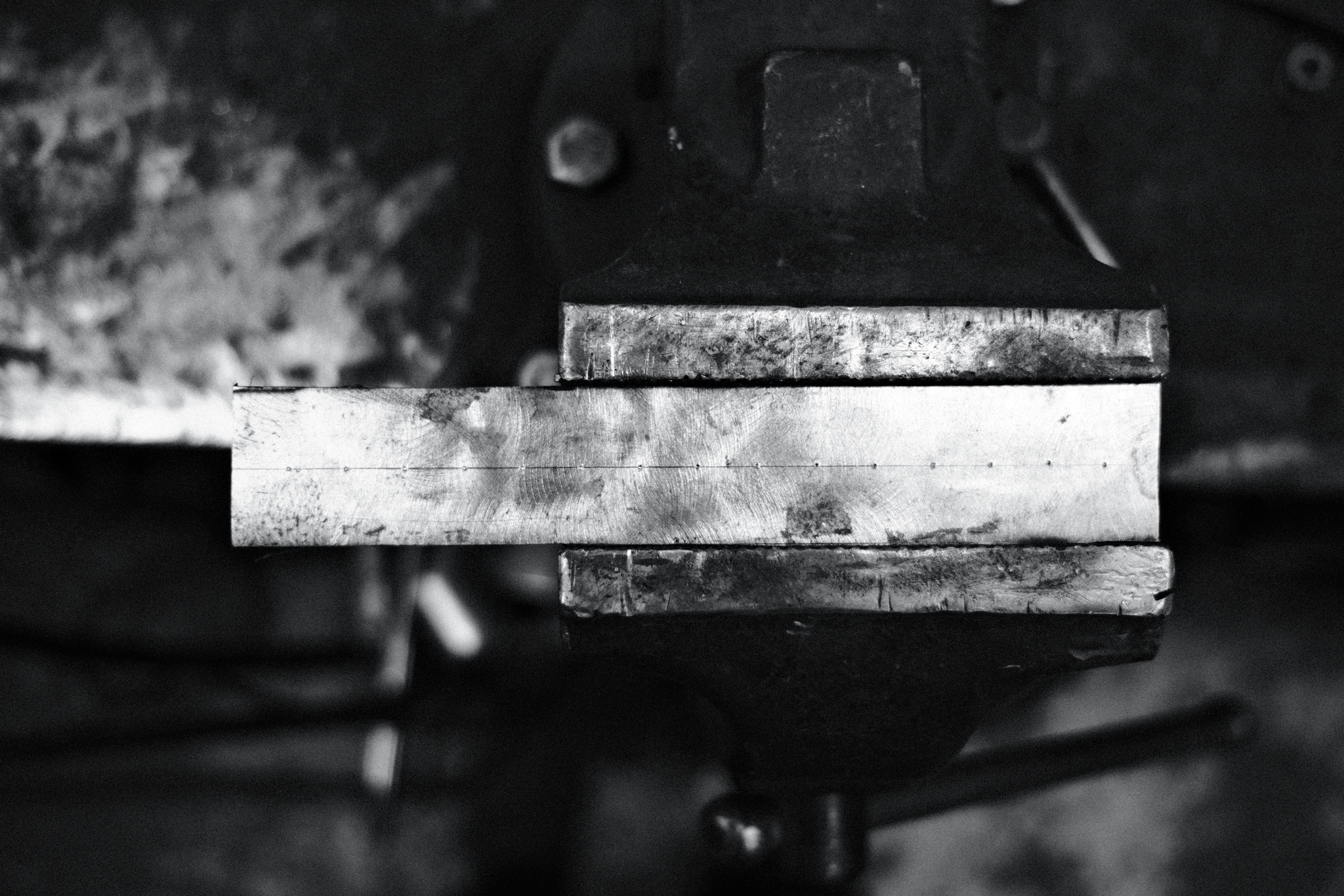
After the piece was cut I traced a line down the middle of it and started laying out the holes I needed to drill. For the spacing between them I measured both the original ones, where the width between varied and some aftermarket ones other people in my garage had. This led me to space them out at 10mm apart.
Once I had layed out all the holes I cut the length so that each end had a hole 10mm in.
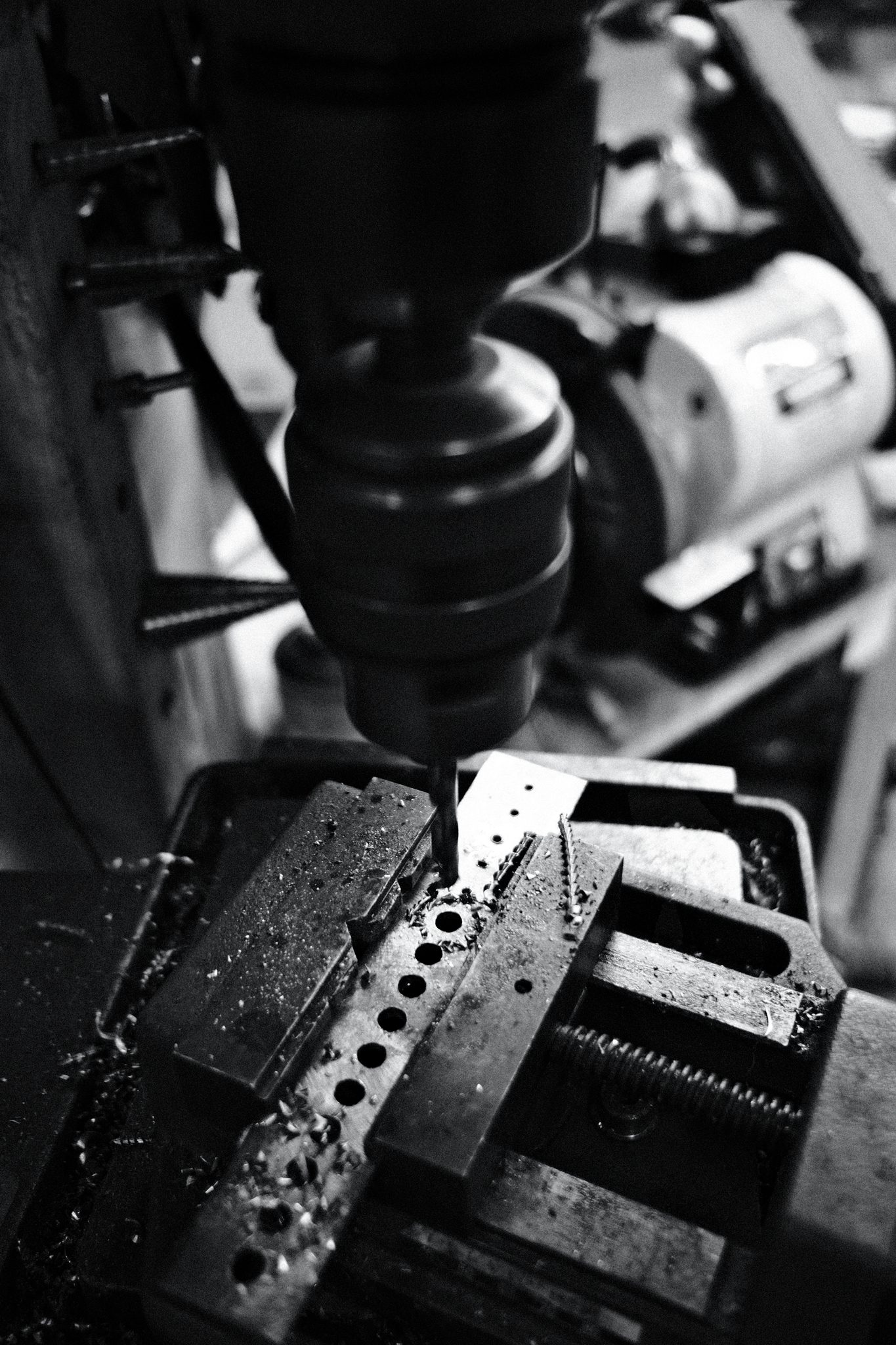
With this done it was time for the drill press. I started with 2,5mm holes and then I used a 7mm drill for the end result.
Once all the holes was done I needed to find something I could bend the metal around to get the right shape of the pegs. As I had created a sketch I could easily go around the shop looking for things that somewhat matched the curve I had drawn.
Luckily I found a hammer that had the perfect curve.
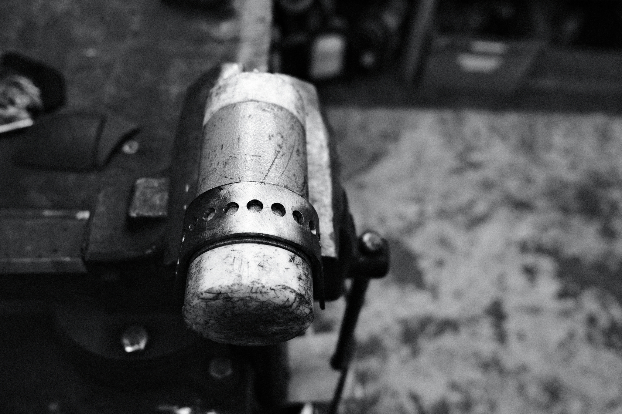
The metal was soft enough for me to just bend it with my hands. Hence it was easier than I had imagined.
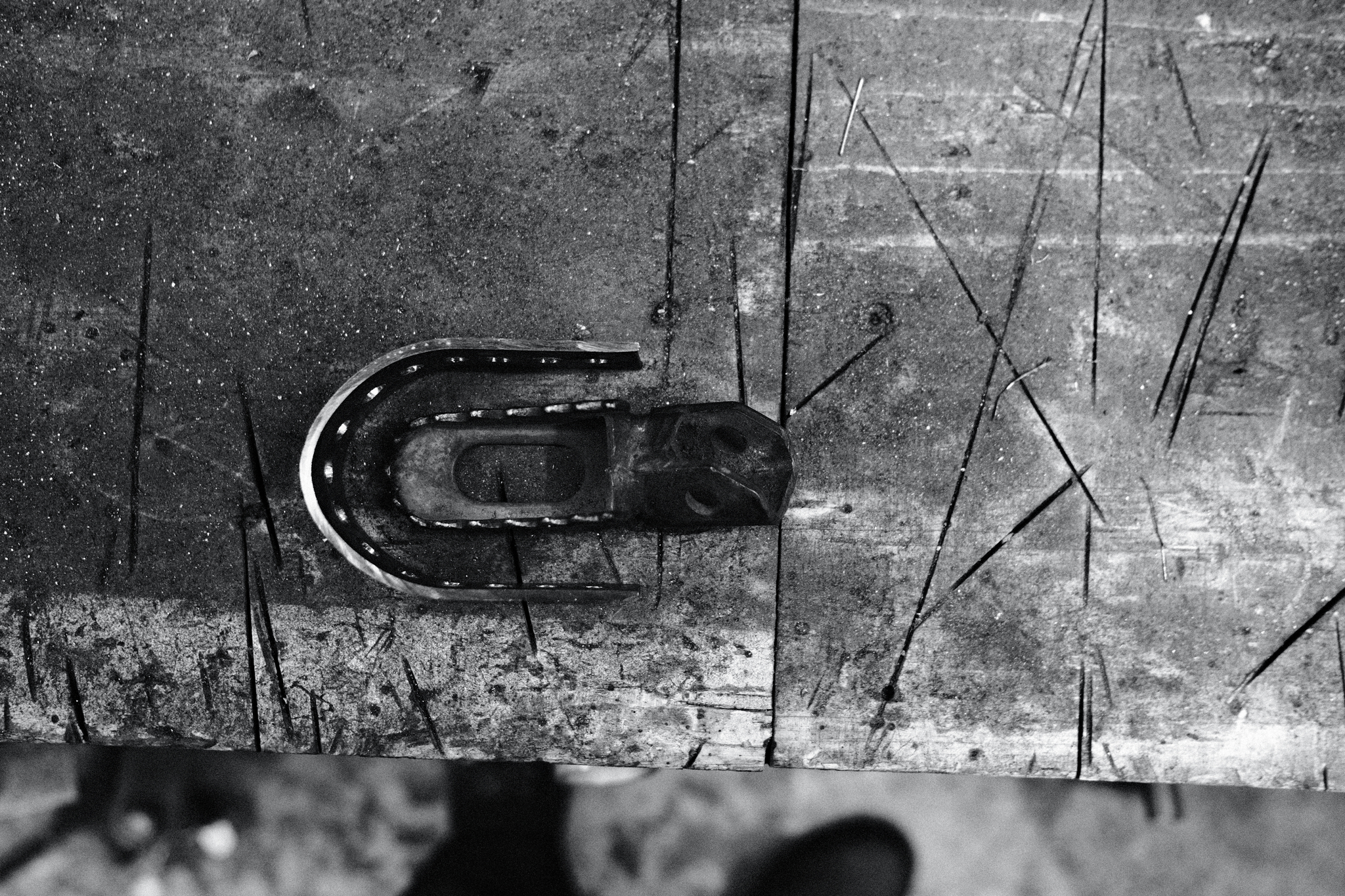
With the bend in the right shape I had to make the cut to separate them as the rest of the process had to be done with each of the sides individually.
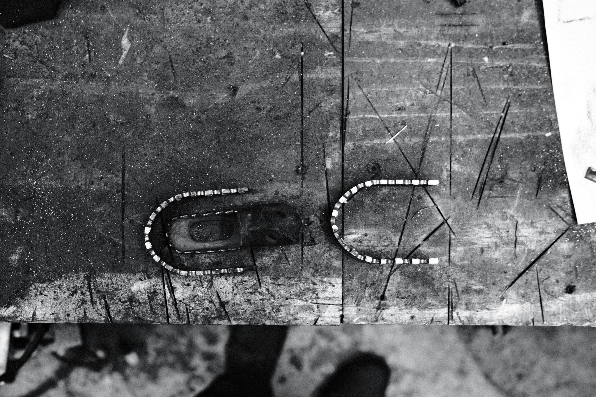
At this point I needed to figure out how to attach them to the original foot pegs. I needed a somewhat strong attachment and also needed to think about the potential bending forces as I now would be creating a wider lever. If I stand all the way forward or back on the new “outer ring” then the beinding forced needs to be absorbed by as much of the original peg as possible.
Hence I created some “deep” mounts closest to the bike that would go a long way below the outer ring and help spread the load.
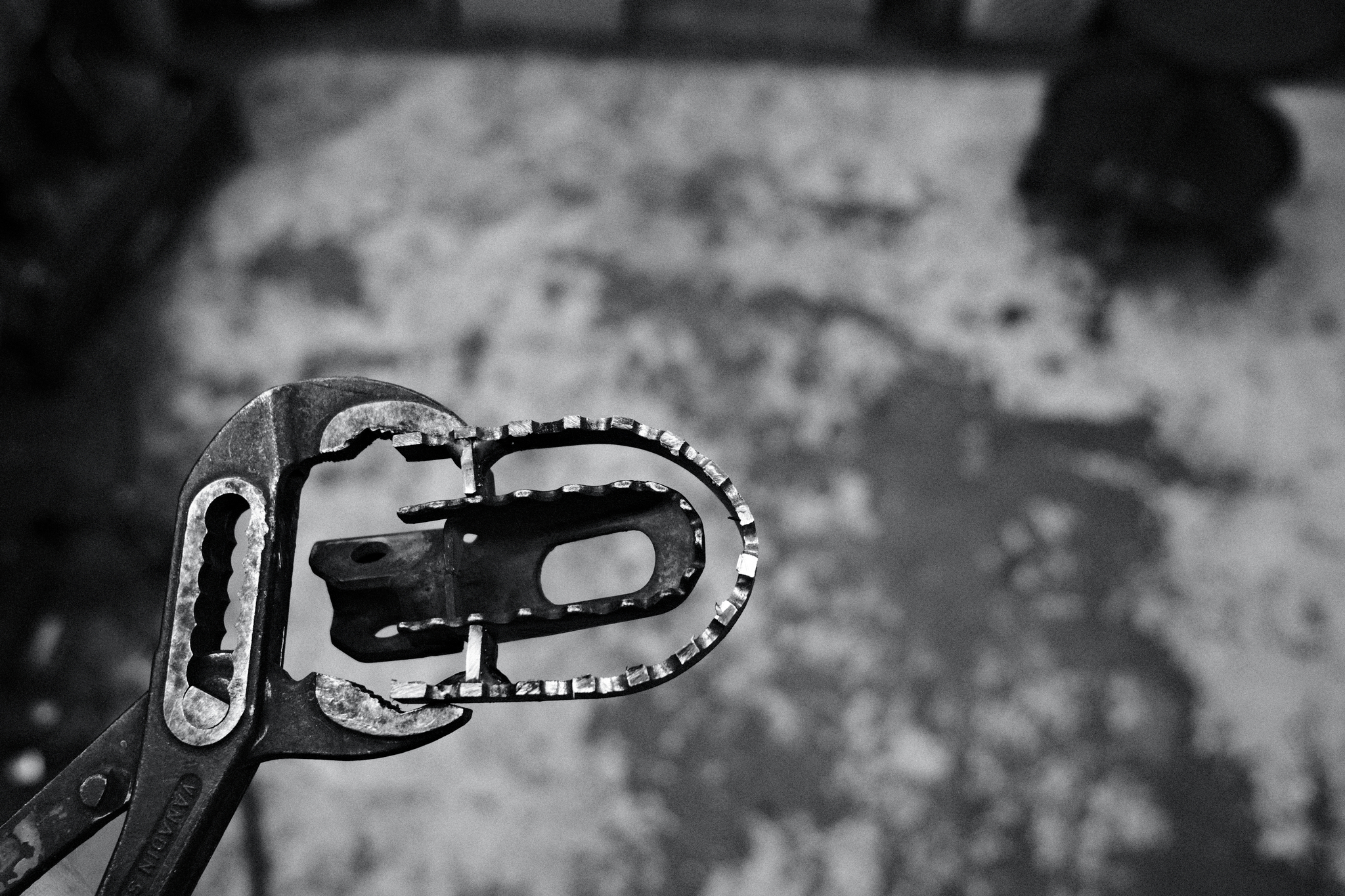
This of course is difficult to see from this angle, but I will try to get some better images next time.
I did not get any farther that this yesterday, so next time I will hopefully get them finished.
I am also not 100% certain on what design I will go for with regards to the mounting points near the end of the peg. It will probably be two mounting point, but whether they will be parallel to the ones closer to the bike or be further out with more of an angle - I have yet to decide.